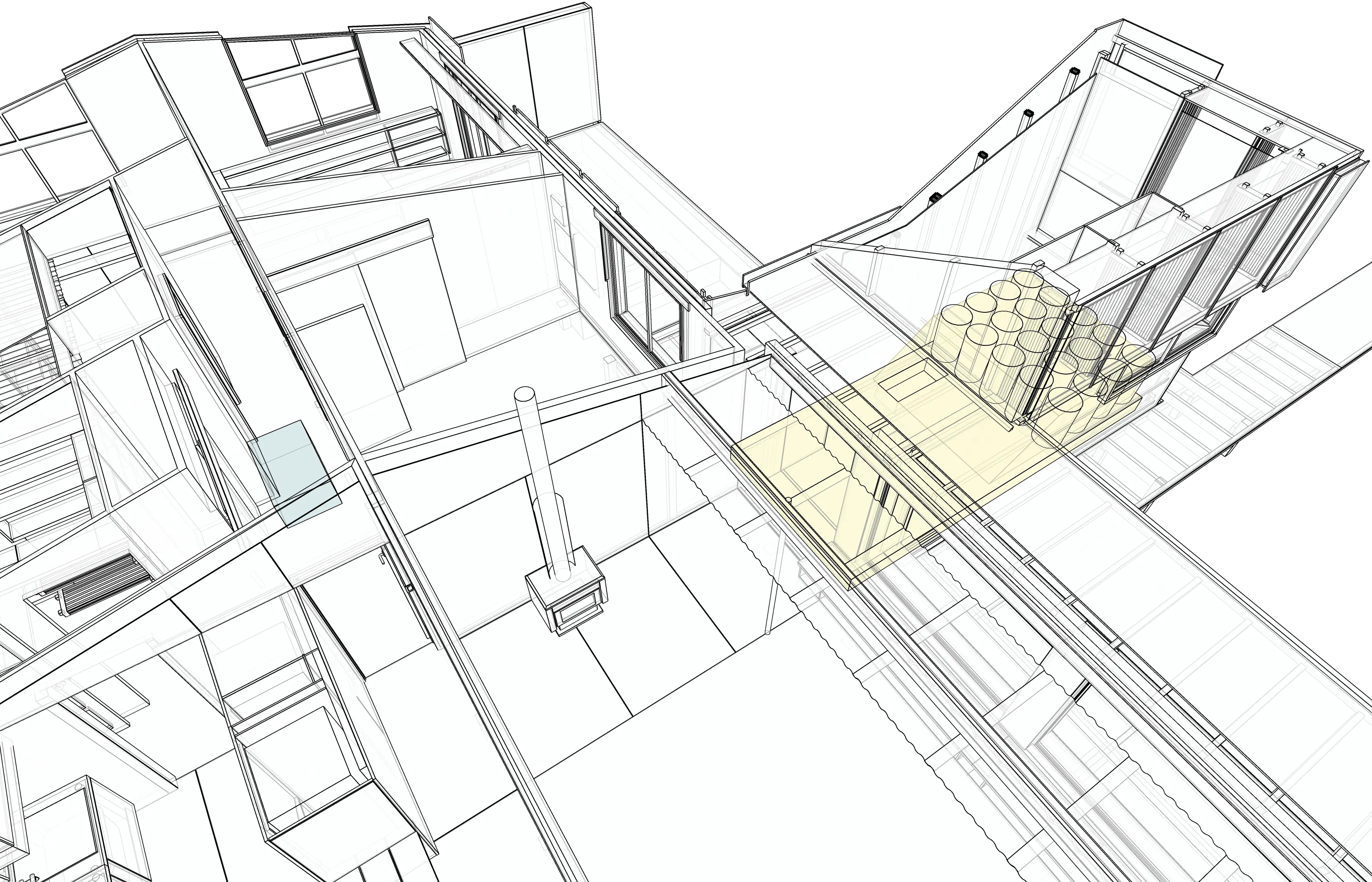
A line of trees on the north boundary prevent solar exposure of the house on winter mornings. To remedy this the Engine Room was added with solar collectors at high level; it acts as a heat exchanger for the entire house.

Airflow on a cold sunny morning

The thermal storage area below includes a 600mm deep concrete manifold, perforated with air ducts, and around 1,000 litres of water in drums, also useful as emergency water in the event of a quake.

Heated air flows into the room via a slot at the top of the inner wall of the solar collector

In summer a flap is opened in the solar collector, which then acts as a heat chimney, drawing hot air from the house.
At night there is no longer a draw from the solar collector and the convection flow stops. Cold air in the collector is trapped, and can’t sink back down to the thermal storage zone.
The system works well, and maintains the house at a consistent temperature for up to 24 hours. If consecutive cold cloudy days occur, we use the original 5.5kW heat pump to top up the mornings and evenings.